DIY Microphone
Needed a good mic
I was looking to replace a free microphone I’d been using for a while. It had quite a bad sibilance effect as I was trying to record something in Audacity. The harshness of the recoded audio was making it hard to listen to and work with. It was taking up a lot of my time to go through and process out harsh tones. So I began looking at solutions for getting a quality microphone for the right price.
Normally when it comes to audio there is a lot of snobbery over high priced gear. Price is always something I look to minimize, and as someone who does not notice a quality decline in highly compressed audio; comparing the sound from a $20 to $400 mic is like (insert meme) “they’re the same thing”.
From my experience with a free mic, I know there is an inflection point where a microphone can be poor enough quality that I just can’t use it. With that in mind I’m targeting getting the highest quality microphone and by any means necessary get it as dirt cheap as possible. I’d heard of people who were tinkerers making quality remakes of older-classic microphone designs that are now public domain.
Finding what I’m looking for
With that in mind I went to go searching for solutions. I was looking for something that would check all the boxes for what were my major concerns.
Concerns
- cheap (always)
- high enough quality to lessen common recording issues such as sibilance
- buy one, not multiple cheap mics (until I find the one that’s not trash)
- has a 3.5mm jack
- If I learn something or have to buy new tools that’s always a plus and practically the goal
Looking around I found a couple of tutorial-build videos.
- A build with a kit from MicParts.com
- A GreatScott video on DIY vs buying
- A DIY Perks video to build for cheap from basic components
Evaluating each build
MicParts seemed to be focused on selling high quality kits that were reproductions of known studio quality equipment. While it looked like a solution that would work I was looking for something that was rock bottom price not just half the price of studio equipment. The GreatScott DIY solution looked like it was a direct relative of my existing free mic. Finally the DIY Perks build appeared to be everything I was looking for.
Winner winner chicken dinner
The main component cost should be around $35, it was using a studio quality capsule-diaphragm, and there was a line out signal that I could modify to a 3.5mm output jack. The whole project included a detailed guide with a design document that differentiated between the microphone diaphragm and the amplification circuit. It was a modular design that I wasn’t afraid to modify. This design addressed every one of my concerns, I had a reasonable understanding of what was needed and it did not shy from explaining the details so I knew I was gonna have fun learning something new.
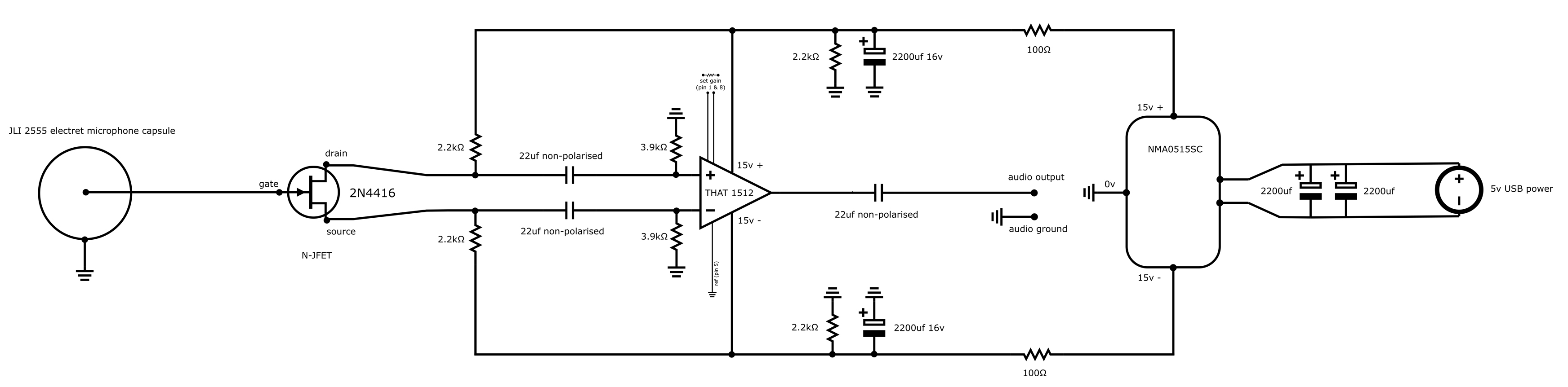 DIY Perks microphone preamp schematic
Remix to suit my needs and cut the fat
I was starting to formulate how to change the build to suit my needs best. There were several parts I wanted to cut out, basically remove the USB audio interface, use a barrel plug instead of USB power and just 3d print my own component housing. The mass appeal factor those things gave to a YouTube video were not the factors that I cared about i.e. price point and functionality.
I went through the parts list and started sourcing all the parts I’d need. There were some of the base parts I grabbed quickly mainly the microphone capsule and the amplifying JFET transistor. Looking at the affiliate links on the remaining parts the shipping was adding up. I put a hold on buying more parts figuring there was a better way to go about it.
Problem with the existing part selection was there were a couple of components that were relatively bespoke where if the design were using standard components it would be easy to source everything in one place like DigiKey or Mouser. I basically needed to find equivalents or replacements for each part in the amplification circuit that wasn’t a resistor or capacitor.
Parts I’d replace
- balanced power supply (gets +/- 15V)
- THAT 1512 Operational Amplifier (OpAmp’s are a common circuit component)
- volume control (could use just a basic potentiometer)
- 3D print or use anything on hand to make the microphone housing
For the balanced power supply I found something for around $10 on amazon with free shipping. It would accept any voltage from 3 to 30 volts. I could easily power it from USB or switch to a 12v supply taken from a WIFI access point.
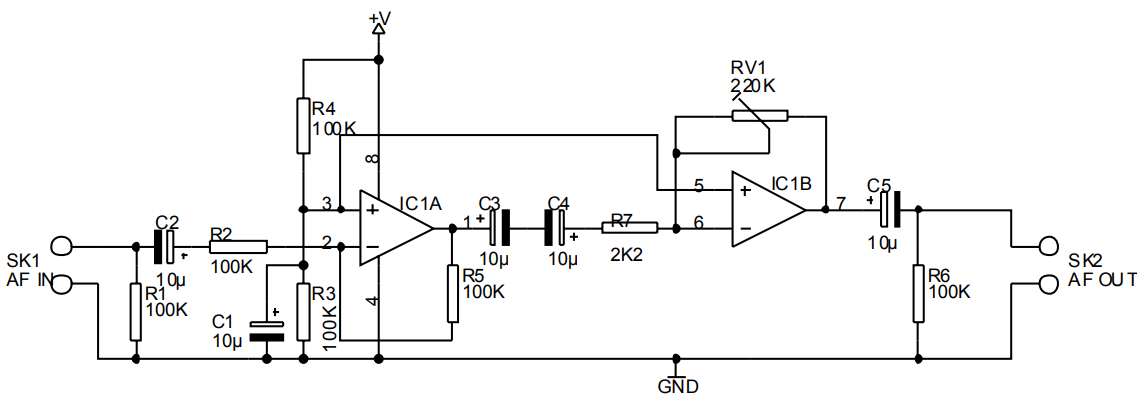 A low cost basic microphone amplifier shematic from Velleman
The OpAmp and circuit schematic for the signal amplifier required a bit more research. I found this design the Velleman K1803 that could potentially replace the amplification circuit. Notably the input signal was not balanced (just like the majority of replacement circuits I found,) but the design included an LM358 as the OpAmp. A popular and cheap Texas Instrument mass produced chip that I could find locally.
I very much liked the balanced nature of the original schematic. It was something I wanted to preserve if possible. The benefit of a balanced signal is how it is protected from EM interference. Consider sending a signal for 5 across the wire. Then in a balanced signal you will send 5 and -5 so when some interference comes on the line and adds 2 then the signal is 7 and -3, but the intended message stays intact because you are looking at the difference between the positive and negative sides. Since the microphone signal starts out fairly weak it seemed good to have this extra protection until the signal was able to be amplified.
So I went to get the LM358 OpAmp, some prototyping PCBs and a couple of capacitors from my local Microcenter. I had everything needed to get started and the first thing was to test the configuration out on the breadboard. I had gone and connected everything up for a test. Did my best to follow the schematic and rewire the THAT 1512 for the LM358 since it was not a drop in replacement. After everything was done it just wasn’t working. Not the biggest surprise being that I’m far more experienced with programming but for sure a big annoyance.
First snag in my plans
I went and changed up the schematic to the Velleman K1803 then back to the DIY Perks schematic and then I finally found it. I was missing a ground from the microphone capsule; the housing was a ground plane as soon as I connected it I got sound. Didn’t sound perfect but I figured well the signal isn’t shielded and probably wasn’t strong enough to drive the speaker I had. (I’ll be coming back to this.)
Start building a microphone
Components of build
- microphone capsule with long wire leads
- microphone housing + arm
- volume controller
- amplification circuit
- amplification circuit housing
After finding the grounding tab for the microphone capsule I was fairly sure it was setup correctly because it is overall a really simple circuit. Thus I began building my own version of the microphone capsule and housing.
Building microphone capsule + housing
Microphone capsule parts
- braided de-soldering wire (had on hand)
- enameled copper wire (used wire from a dead 40mm fan I had. Wire was thinner than hair broke several times regret not just buying really thin silicon cable wires)
- a spare audio cable (it was not making proper connection so I was happy to reuse it for something)
- brass wire mesh (purchased)
- a thin brass strip was replaced with nickel strip (had on hand)
- 2-3mm brass rods used for suspension hooks (purchased cheap hobby supplies from local hardware store)
- rubber O-rings to suspend and absorb vibrations (purchased)
- 3d printed a cage to surround the capsule (I purchased the cheapest option for a brass mesh. It could have been deformed and crushed easily so I needed something to protect the innards)
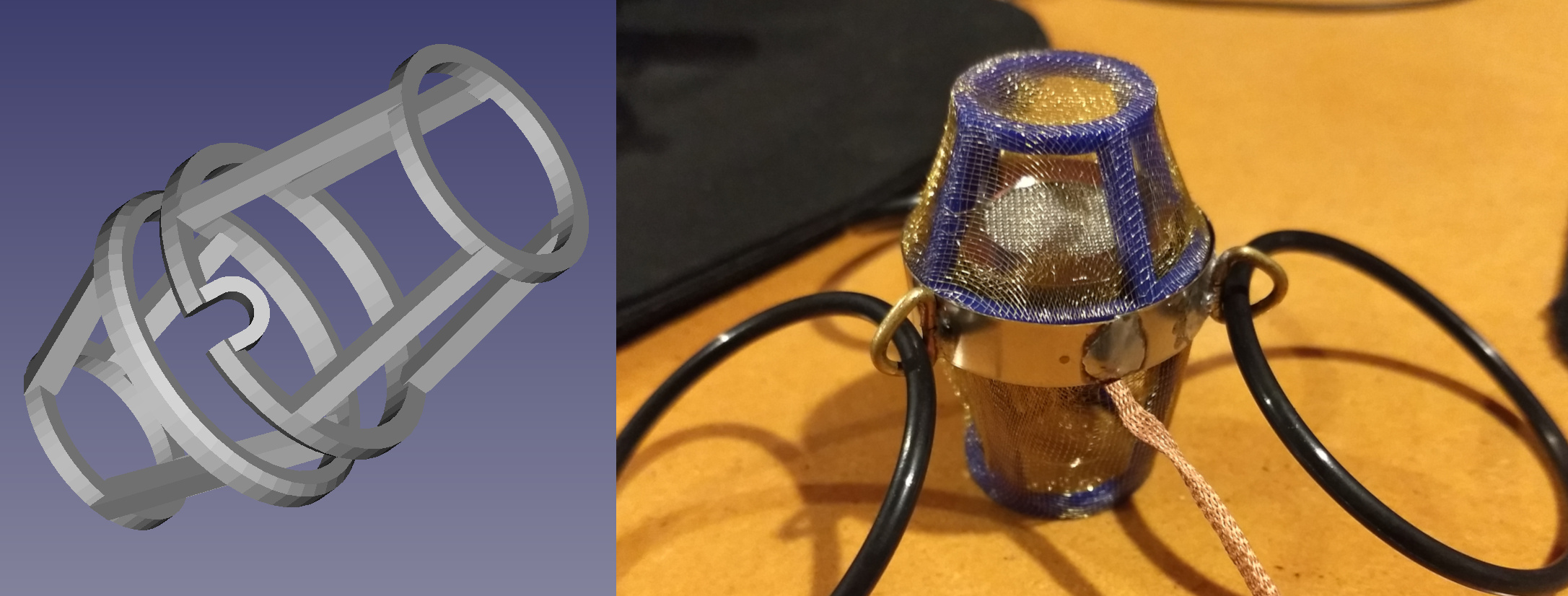 3D printed protective cage and Microphone capsule component
With all of this I effectively remixed the original design to use as many parts that I already had on hand. Although I could have lived without the days of stress from struggling with breaking copper wire thinner than a strand of human hair. Ignoring that, it came out as something I could say I’m proud of.
Building microphone housing
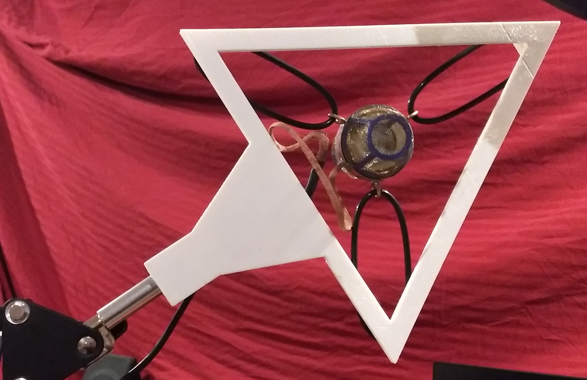
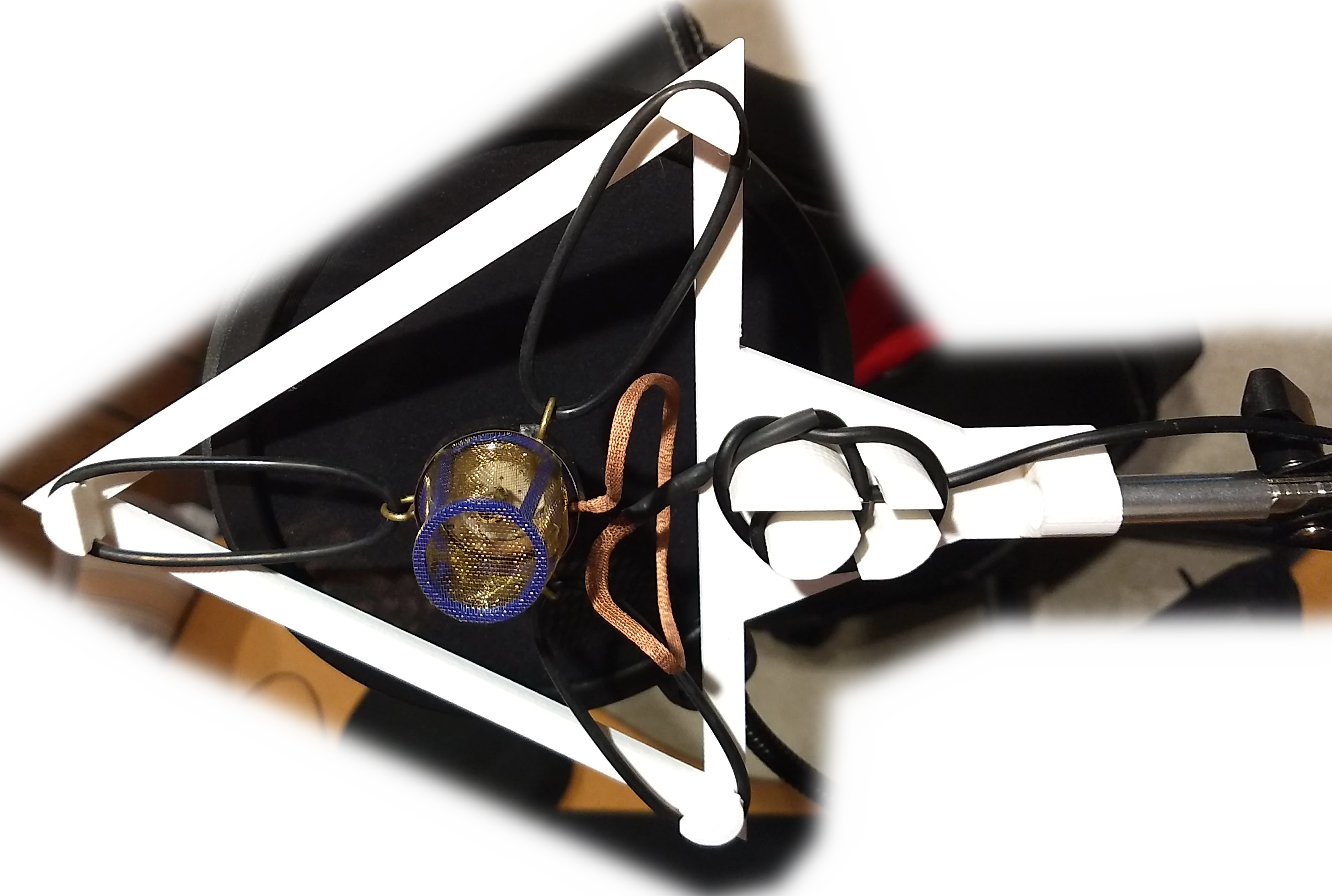 3D printed housing to suspend microphone capsule. Has a cable hold-knot and microphone arm connection
There was just a little bit left for the housing. Mainly an adjustable arm and a support for the O-ring suspension system. I had the idea to just get a desk lamp arm similar to the Pixar mascot and repurpose it. I was surprised by the price a simple lamp was going for. I ended up with a real mic arm because they were going for about the same price and for $10 extra I got a full mic kit to play with for dirt cheap.
This was the first of my initial goals I’d break “buy one, not multiple cheap mics” and it wouldn’t be the last. I could have lived with just using the kit I’d gotten but I was determined to finish what I’d started. Somewhere in between sunk cost fallacy and knowing there was more to learn from this experience I kept moving on.
Building amplification circuit
Next there is the amplification circuit; I was thinking I had everything figured out. I was moving forward with mapping out where the connections on the prototyping PCB would go. I soldered in a few components mainly the LM358 OpAmp and a few capacitors, twist tying other ends to complete the circuit. Getting it to a state that was just good enough to check how the mic would end up sounding and it didn’t sound any good.
Mic failing tests, start debugging issue
Went over what could have gone wrong
- Broken part
- lack of shielding
- Misunderstanding of OpAmp circuits
Testing if there was a lack of shielding was relatively easy I picked up the circuit and put it inside a grounded pc case. It sounded the same so I crossed that off my list. It was possible I damaged the LM358 by soldering it directly to the PCB instead of using a 8-pin DIP socket to install it. I went perusing for prebuilt audio Amp circuits half looking for a replacement circuit and half looking to understand more.
Taking the time to play around with the mic kit I recently got I ended up taking apart it’s microphone to trace how it was designed. It was not using a balanced signal from the microphone capsule but after reviewing enough circuits I figured out how I’d wire up my balanced mic to work in a non-balanced circuit. I used some alligator clips to connect my mic capsule in parallel with the one on the cheap mic. I went to speak into my microphone and thought my voice projected louder than normal. After a minute of testing I could tell my capsule was working perfectly. It was just hard to tell initially with it being so clear and having almost zero delay being processed through such a simple circuit.
Design mistake
Hearing such a clear signal without any shielding didn’t tell me what was specifically wrong but let me know that I had definitely made a design mistake. Remembering how my first test of the circuit on a breadboard was not sounding perfect and I thought the signal would clear up with shielding. Well this now proves to me the signal should have been fairly pristine from the get-go. Thus my modifications to the OpAmp were surface level and just looked reasonable but were missing some key facts about how OpAmp circuits work.
Researching and learning more about OpAmps
It was time to go back to the drawing board and reevaluate my use of OpAmps. After going through quite a few tutorials on OpAmps and learning the basic circuits used for OpAmp designs. I now had a grasp on where I had gone wrong and what assumption lead me astray.
It appeared that the THAT 1512 was not a standard OpAmp but one that was specifically designed for audio. It abstracted away the feedback loop that’s needed in a standard OpAmp to control the voltage gain. Otherwise it will just do it’s base amplification and for the LM358 that was 100k. It appears that the amplification is so high because it is not intended for audio but for logic. It boosts the signal so drastically because it’s trying to hit the voltage ceiling. This chip was designed with binary logic in mind so for normal use there’s only two states zero and max voltage.
Replace & redesign OpAmps circuit
After going and expanding my knowledge on OpAmps I found NE5532 an equivalent to the LM358 that was audio grade. It was classified as low-noise, it had the same pin-out and I had seen it used in a couple of other audio schematics. I ended up purchasing it with a lot of other spare components from DigiKey. The shipping was higher than the part cost so I grabbed a bunch of extras to justify it and slowly inching up my overall costs out of the cheap category. Plus I upgraded my soldering station after all the trouble I had dealing with the enameled wire.
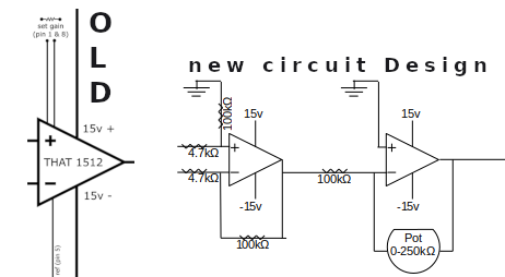 Old THAT OpAmp and circuit redesign
The redesign was not overly complicated. Finding a amplification circuit for a balanced input was not in the basic examples but when you know what your looking for it is only a quick google search away. We start amplifying the balanced input and the difference in the resistor values give us a signal gain of about 20 to bring the volume up to a normal level. It’s now no longer a balanced signal but just a single line output. We can feed that back into the second OpAmp on our integrated circuit and use a potentiometer as a volume control.
I have a good design now that passes the breadboard test. The mic is sounding good and now I’m left to get assembling things.
Finishing the build
At this point we firmly know everything is working with only the amplification circuit and its housing left to go. I map out how all the components are to be connected on the prototyping PCB. Black is ground, green is +15v and the orangish red is -15v.
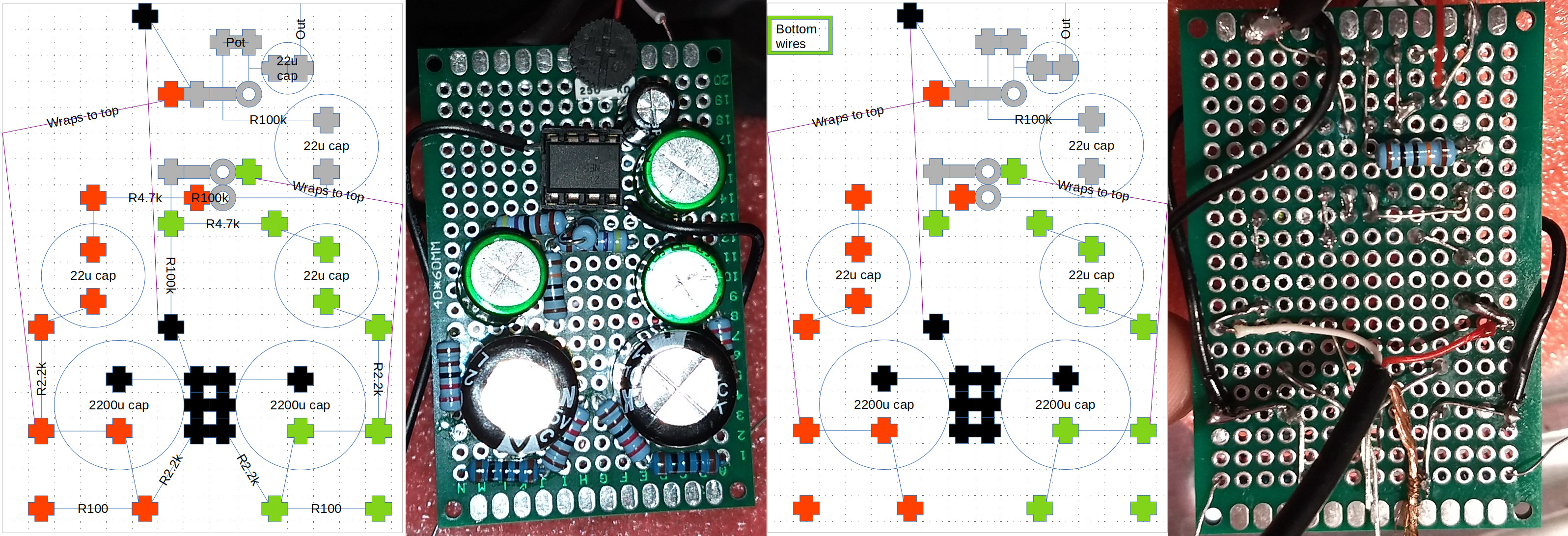 Planned out wiring to use smallest PCB available. Front and Back of the final amplification circuit
I solder in the balanced power supply attaching it to the 100 ohm resistors on each corner while not forgetting to connect the ground plane. That finalizes all the circuits, now we just need to place them in some protective housing. I print 3 boxes, one to hold the balanced power supply, another for the amplification circuit and the last one is a big box to hold everything. I use the brass mesh for shielding each component, so the power supply and amplification circuit are in separate zones to further protect the microphone signal from interference.
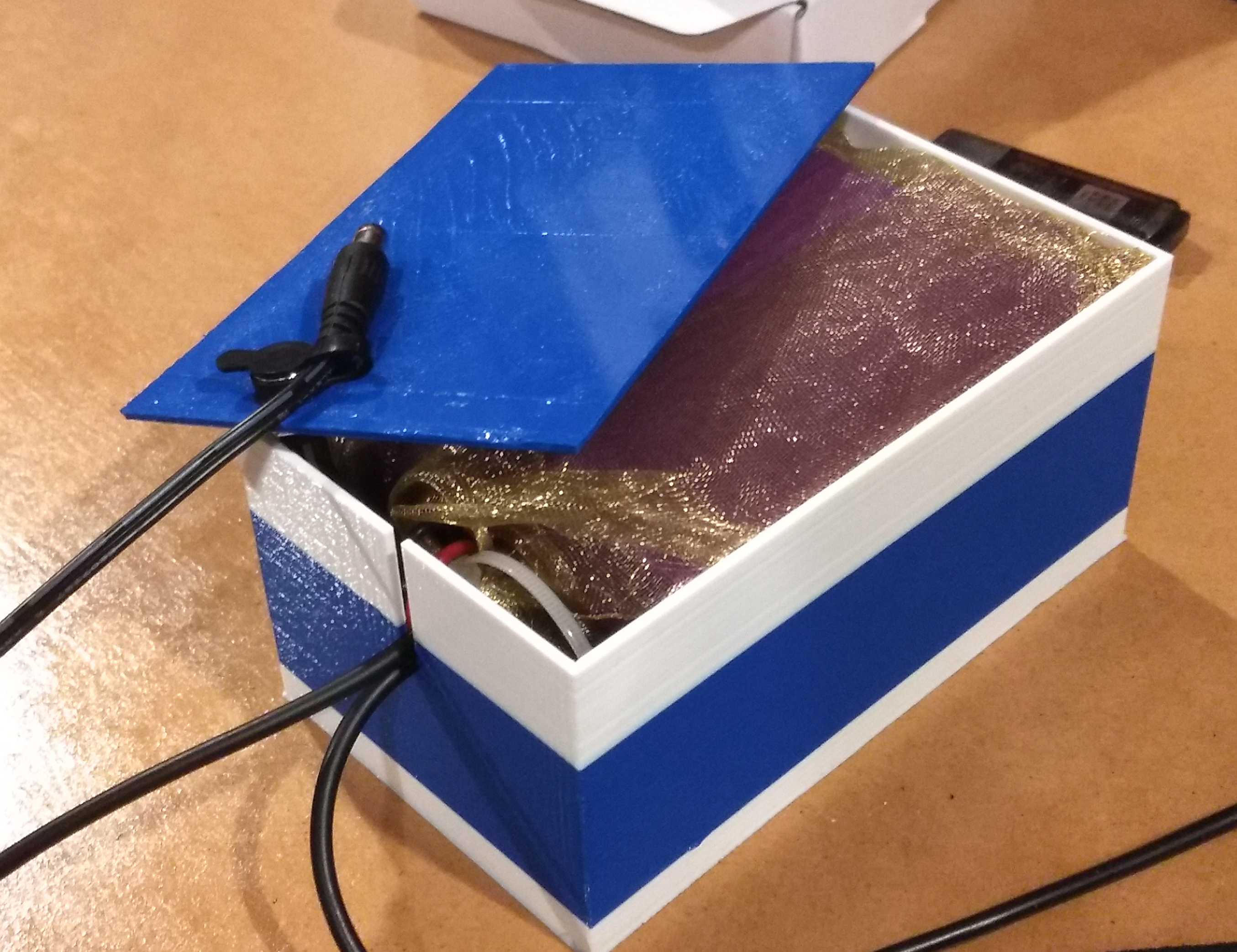 Final box to house amplification circuits. Contains separate boxes to shield the power supply from the OpAmp
Plug everything in give it a go and enjoy the crisp clean sound of a DIY microphone.
Conclusion
I’m quite happy with what I was able to build and it ended up as quite a journey with ups and downs along the way.
Reevaluating my initial concerns
- cheap
- high enough quality to lessen common recording issues such as sibilance
- buy one, not multiple cheap mics
- has a 3.5mm jack
- If I learn something or have to buy new tools that’s always a plus and practically the goal
I could definitely say there were some mistakes and lessons learned along the way. While I ended up with a unique end product it was overtime and over budget. For my own time doing hobbies that’s okay, it’s the time to chase rabbit holes and be opinionated about how I’d like something to work. Overall I’m just conjuring up thoughts on how a lot of big development projects have to start somewhere and you don’t know the scope of issues you’ll run into until the project is mid flight. Often I’ll start a project similarly, I go and research a topic until I know just enough to be dangerous and that normally works out pretty well. I’m not immune to snags in a project, but any project has it’s base assumptions and when you find things are not working when everything should be fine. Then it becomes a problem that cascades where you need to do your best to isolate, reevaluate and track down why.
Here now standing at the finish line I can say that was neat and I know more for having done it. Now lets never do that again, take the easy route next time. After spending time researching DIY mics I’d tell anyone there is a better way that is dead simple and dirt cheap. I found it after getting well into the project at the time I was determined to complete the build i started. Mentally I knew this was a far superior method to address all my concerns except as a dead simple solution there would be less to learn.
If I could go back and take the easy route I would. It would put over two hundred dollars in tools and parts cost back in my pocket. Also if I’m going back to do it I’d retain everything I learned, but that’s the point, to learn.